I wanted to 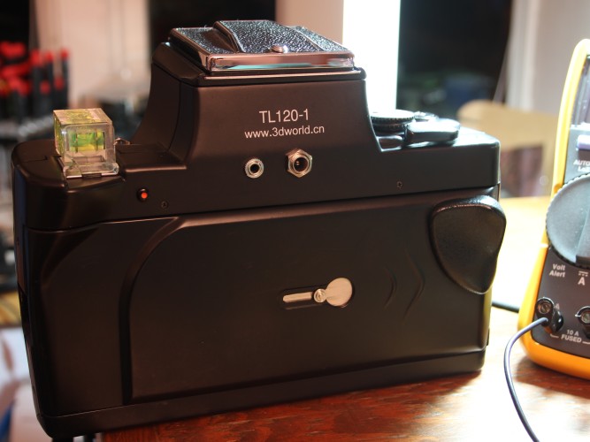 explore the options to free the TL120 from the limits of its little button cells. I don’t have a pressing need for long exposures, but I have had occasions when being able to connect a nice warm battery would have been nice.
Power
Earlier experiments show the TL120 meter dissipates about 30 milliwatts, while its shutter consumes about 75 milliwatts. The experiments also show that the camera works as expected with a supply voltage between 2.0 and 3.3v. Because the button cells would not be expected to deliver higher voltages, it didn’t seem prudent to push my experiments to higher voltages.
Design Constraints
The modest power requirements were not going to be a significant constraint. Any battery larger than a pair of button cells would be an improvement and there were several ways to accomplish this.
An internal battery pack with an external charging jack is interesting from the stealth and technology perspectives. The camera would be hard to distinguish from the stock camera, and playing with small lithium cells and chargers would be fun. But, it would mean the camera battery might be dead when it was wanted, and stealth is seldom in demand when shooting with the TL120.
There is space in the base of the TL120 for a removable internal battery pack. But the required work on the case would be difficult to complete neatly. This seemed too complicated to consider seriously.
I chose to pursue an external battery pack through a dedicated power jack. Taking the simplest option, I chose to wire the external power in parallel with the button cell battery. This would let me ignore considerations of the safe or correct location to connect power. If the factory supplied power to a connector, so could I.
 To provide some flexibility in the choice of external battery, I chose to incorporate a voltage regulator. By doing so, the external battery can be anything which delivers between 5 and 32v. It could be a 5v USB port, a 9.6v cordless drill, or a 12v car battery. Simple linear voltage regulators boil the excess energy off as heat. This isn’t a huge concern with the current the TL120 needs, but there are now more efficient choices. In particular, the TSR 1-2433 from Traco Power which accepts anything between 5 and 32v and can deliver up to 1a of 3.3v.
  Yes, it is overkill here, but it is an awesome little device and it seemed like a fun thing to try.
In this design, the batteries should be removed when using the external battery. They probably would not be damaged by a small charging current, but since there is no current limiter in the circuit, it is possible that the external battery will deliver enough current to cook the little button cells. The diode was added to the circuit after observing the small parasitic drain of the TSR 1-2433. Because it is being used as a simple blocking diode, the choice of diodes isn’t critical. Something with a small forward drop is desirable. I used an extra 1N-4001.
Installation
Having been inside the TL120 before, I knew there was space under the finder for additions. Disassembly is covered elsewhere. Go slowly, and have a muffin pan with labels handy to store the removed fasteners.
Connection Points
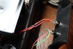
The circuit board in the bottom of the camera has sixteen numbered solder pads. Ground (battery negative)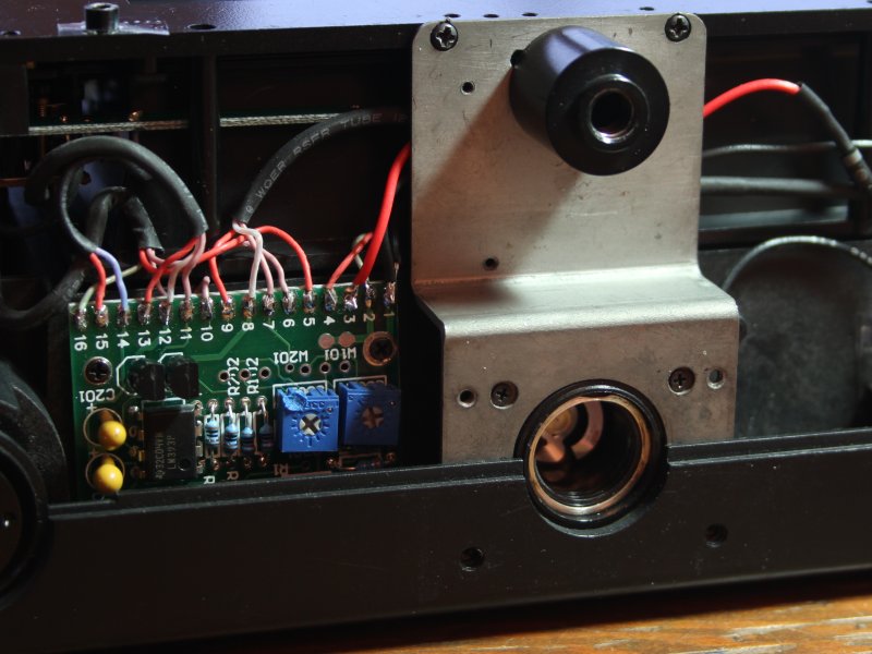 is available on pads 1 and 2. Battery positive is fed on pads 3 and 4. It is a simple matter to feed two additional wires under the tripod mount and tack them in place here.
Another option is to use the back of the battery holder. Remove the tripod mount (four small and two large screws), turn it over, and connect your wires to the exiting lugs.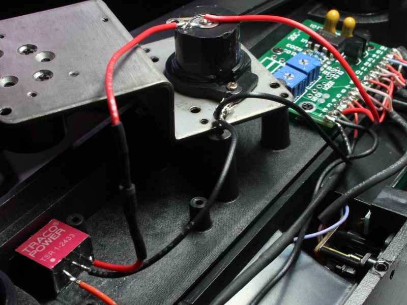
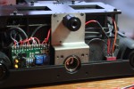
I chose to locate the power jack under the finder. I had already installed a flash connector so I knew there was extra space available. When placing the jack, take care to position it high enough to clear the camera frame and low enough to clear the mirror. This would also be a reasonable place to locate an on/off switch if one is desired.
Mounting Points
I had planned on locating the voltage regulator under the finder and running 3v down to the battery holder. I opted to install the regulator in the camera base where there was a solid corner into which it could be fixed. I used double-stick tape (and foam blocking) to hold it into place. Some glue is probably a better choice, but I was too impatient to wait through the curing time.
The blocking diode was added after the initial assembly. It is simply soldered in-line and left to float with the wire.
Labeling
Being a DC connector, polarity matters when using an external battery. I wired my connector to be positive center, but there is no reason it couldn’t have been done with a negative center. The back of the camera should be labeled to indicate this, and to recommend removal of the button cells when using the power jack.
Performance
The TSR 1-2433 behaves as expected. It begins delivering 3.3v when the input voltage exceeds 4.1v. If the input voltage then drops, it will continue to deliver 3.3v until the input falls below 3.4v (at which point the output falls to 0v).
There is a 1.4ma current drawn on the output when it is connected in parallel with the button cells. This is a significant parasitic load on cells with a stated capacity of 150mAh. By placing a small blocking diode on the positive output of the TSR 1-2433, this current drops to an unmeasurable level. When using a 1N-4001 diode, the no-load output drops to 3.01v, which falls to 2.57v when powering the shutter. This is well within the voltage seen on the stock cells and safely above 1.2v where the shutter has been observed to cease working.
