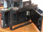
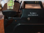
From the outside, the TL120-1 is a pretty intimidating beast. However, it isn’t that difficult to get inside should you need to do so.
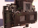 The camera can be carved up into five major pieces:
- Viewfinder
- Lens board
- Front skin
- Back skin
- Guts
You’ll need a pair of tweezers, as well as #0 and #1 cross-head screwdrivers. While I don’t think the screws are actually Philips, such drivers fit fairly well. There will be several different types and lengths of screws. Get a muffin-tin or some other parts tray with labels and keep them all sorted. There are differences in length, head size, and thread type, and they all need to get back in the right place.
In the following description, any mention of left/right/top/bottom are written from the perspective of someone holding the camera in its operating position. It may not conform to left and right in the provided picture.
Remove the battery cover and batteries before doing anything. I’m not providing a picture of this step. I’m assuming that anyone willing to rip into their camera already knows how to replace the batteries.
Viewfinder
Regardless of what type of finder you have on there, it can just be unclipped and set aside.
Lens Board
The lens board is held on with either four or five screws. The older cameras have four, the newer cameras have five.
Lay 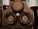 the camera on its back, loosen the screws and lift them out with your tweezers. When you are doing the screws, loosen one just a little and then move on to the next. Work your way around the board so they all are loosened fully at about the same time.
On older cameras, the lens board will now lift off the front of the camera as a single unit. Set it aside somewhere safe.
On newer cameras, there will be three wires soldered to the viewing lens. These wires transfer the aperture setting from the lens board to the meter circuit in the body. The same signals are transferred in the older cameras, but they pass through three spring-loaded contacts rather than by soldered wires. Subsequent pictures in this sequence are from an older camera so the lens board can be fully removed. With a newer camera, you’ll need to decide if you are going to unsolder the wires, or leave the board attached and just work around it.
The lenses can be removed from the lens board, but if you do so there is a high risk of un-syncing the focus or apertures. Unless there is something wrong, leave them alone.
You can now start to see the guts of the camera. There should be one standoff for each of the lensboard screws you removed. These will be about 3mm tall and appear to be attached to the camera. They aren’t really. They’re held on with a little bit of double-stick tape. Remove them (before they fall off into the carpet) and store them with the screws.
Front Skin
The front skin is made of thin plastic. It really is just a skin over the metal guts. The carrying strap lugs come 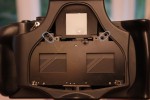 through holes in the skin and are attached directly to the metal guts. Remove the four screws (two each) and lift the left and right strap lugs out of the camera. In the picture, the lug screws are circled and the left lug has already been removed.
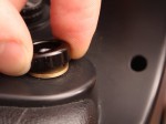
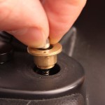
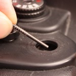
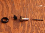
The shutter button is the next to go. The black trim ring simply unscrews (normally threaded) and the black button underneath lifts off to reveal a brash bushing. A pin spanner could be used to unscrew the bushing, but chances are good that a sturdy paperclip will provide enough leverage to loosen it. Finally, lift out the rod and spring. Make sure you get the spring. Don’t let it fall inside or fly across the room!
 |
 |
 |
 |
There are two screws on the face, one below the shutter speed dial and the other below the hot shoe. The included photo only shows the one under the shutter dial, but remove both.
There are two more on both the left and right sides. The right hand screws are set deeply in the rubber grip. Probe gently for them until your screwdriver tip is correctly aligned. The screw heads are pretty soft. If you just start spinning the driver, you will likely mung the head.
There are two more at the bottom of the camera at the battery compartment. These screws, unlike most others on the camera, thread into metal.
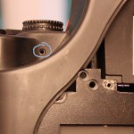 |
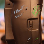 |
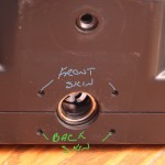 |
On both the sides and the bottom, there are nearby screws which retain the rear skin. If you are going to pull the rear skin, you can go ahead and pull these now.
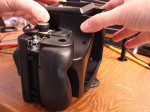 Now you can separate the front and back skins. It is significant that the viewfinder frame is neither front nor rear. It is attached to the guts of the camera.
Grasp the viewfinder mount with one hand, the front skin with the other, and gently wiggle the front off. The only thing that might catch is the tripod mount, but that should be obvious. It really should just slip apart. Watch for small wires around the shutter button and the hotshoe.
Back Skin
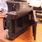 After the front is off, the back is fairly easy to remove. There are two screws on each of the back, left, right, and bottom. The earlier photos have shown a couple of these (marked in green) and the rest aren’t hard to find.
The significant part of the removal of the skin is that the door remains attached to the guts. The door does not travel with the skin. Unlatch the door, swing it open and the skin will slide off over it. The wires to the hotshoe will prevent the skin from being removed completely, but there is enough length in the wires to let the skin swing fully off the camera.
The Guts
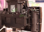
The guts are now revealed for your inspection.
 |
 |
Add a flash connector
The TL-120 has a hot shoe. I have no idea why they did not also include a flash connector. Since we have it open, there’s no real reason not to toss one in. The PC flash connector may have been hot stuff in the 1920s, but it is a connector whose time has gone. 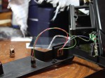 A 3.5mm audio jack is a much better choice. The cables are cheap, the jacks are cheap, and the connection is solid.
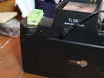
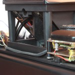
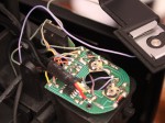
There is plenty of space under the mirror in the finder, so I drilled a hole in the back of the case and dropped an 1/8″ jack in. I cabled it over to the hot shoe so that the back of the camera would come off the same way the next time I came in here. The shoe is held on with four little screws, and by taking it off, I was able to solder additional wires to the terminals without melting the case plastic.
 |
 |
The new connector works perfectly. It is wired in parallel with the stock hot shoe, so both are active and neither interferes with the other.
Some things of note
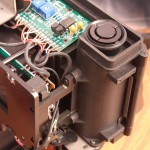
- These cameras appear to have been each assembled by hand. I’m not surprised there were so many different versions of them.
- There is a lot of space available under the view finder mirror. I will probably try to incorporate an external power and flash connector in there. There’s no reason a power switch couldn’t be fit as well.
- The wiring is done with very stiff, sold-core wire. It isn’t very pretty, but it does have the advantage that it will stay where it is put.
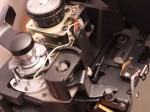
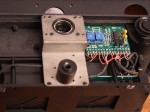
- The tripod mount is screwed to a substantial steel plate which is screwed to the guts of the camera.
- There was space in there for much larger batteries.
 |
 |
|
 |
 |
 |
Reassembly
Putting it back together isn’t really much different than taking it apart (in reverse). A few things to look out for:
- There is a washer above the spring on the film advance lever. Be sure it goes under the skin.
- The metal “spring” behind the take-up spool folds over the side of the camera and forms a tab behind the hinge. Be sure the skin sits in front of the tab of metal.
- The wires to the flash connector will be easy to pinch.
- Tighten the screws little by little in rotation. Avoid the temptation to tighten one down and move on to the next. You want everything to snug up and align, not be twisted into compliance.
- Pay attention to the different screws! Some are threaded to go into plastic. Others are cut for metal. Be sure you are putting the right ones in the right holes.
- Most of the screws thread into plastic. Don’t over tighten them!
