|
|
I have included file sizes in the image links. Please take a moment to check these sizes before you begin downloading images for viewing. Several of the JPS files are very large and will be painful to download over a modem link. The images are presented in cross-eye
and anaglyph format. If you prefer a different format or size, please give
the Stereoscope applet a try. |
|
|
|
|
[ Back ] [ Next ]
Determining Switch Functions
Attached to the top of the rear skin, you will find a small circuit board
that has the push buttons, control dial, and shutter release. By pulling
four silver screws, you can gently fold the circuit board down to get to the
shutter button. There are control buttons that remain cemented to the rear
skin, so be careful when folding the board down.
This is where the action is. It took quite a while with a VOM and some
extra hands decipher it.
 |
|
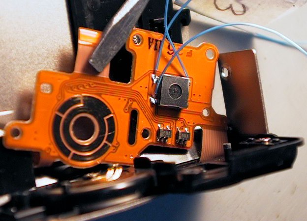 For
version one, I used some "wire wrap" wire to extend contacts 1,3 and
4. Unfortunately, I had only blue wire and other colors weren't available
in Juneau. Therefore, I had to tag each wire before soldering it in.
This will make working on the leads much more difficult later as I will have to
remove the tags when I'm all done.
For
version one, I used some "wire wrap" wire to extend contacts 1,3 and
4. Unfortunately, I had only blue wire and other colors weren't available
in Juneau. Therefore, I had to tag each wire before soldering it in.
This will make working on the leads much more difficult later as I will have to
remove the tags when I'm all done.
For version two, I used the cables I cut off of a set of super cheap "ear
bud" head phones. They provided me with very flexible four conductor
cable with molded 1/8" stereo plugs already attached. Except for
cramming the extra bulk of the wire around the shutter buttons, it is a far
superior to "wire wrap" wire. In all, though, this is delicate
work (that's a 1/4" screwdriver weighting down the circuit board). I
used the smallest tip on my temperature controlled Weller iron, and it was still
too large. This is not a job I would attempt with a 25 watt pencil iron
from K-Mart.
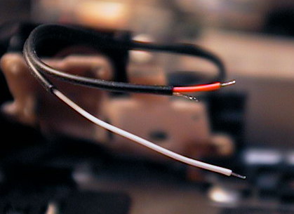 |
These are scenes from the assembly of version two. To the left, you can see three conductors from the headphone cable, stripped and ready for action. To the right, the routing of the newer, more flexible cabling. As I wanted to retain full stock shutter button control, the real trick was maintaining sufficient space around the switch for the mechanical button to clear. | 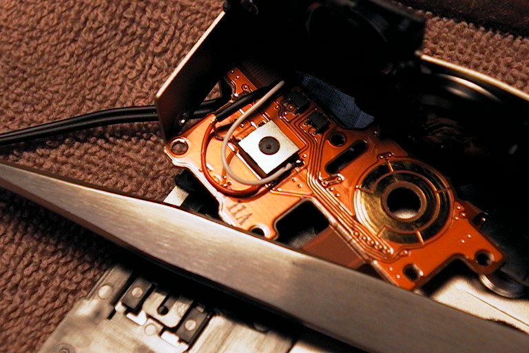 |