|
|
I have included file sizes in the image links. Please take a moment to check these sizes before you begin downloading images for viewing. Several of the JPS files are very large and will be painful to download over a modem link. The images are presented in cross-eye
and anaglyph format. If you prefer a different format or size, please give
the Stereoscope applet a try. |
|
|
|
|
[ Back ] [ Next ]
Disassembly
Thanks to the metal construction and lots of screws, pulling the skin off of an A5 is a fairly simple task. Remove the battery, flash card, and screws. Remove the front skin. Unclip the control panel connector and remove the rear skin. Sounds simple, doesn't it?
Bottom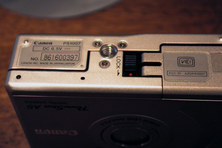
|
Right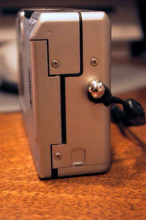
|
Left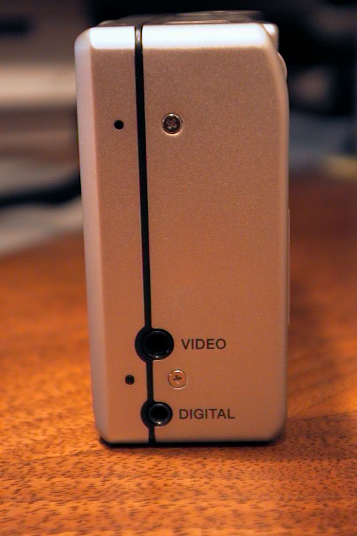
|
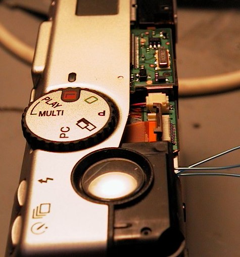 |
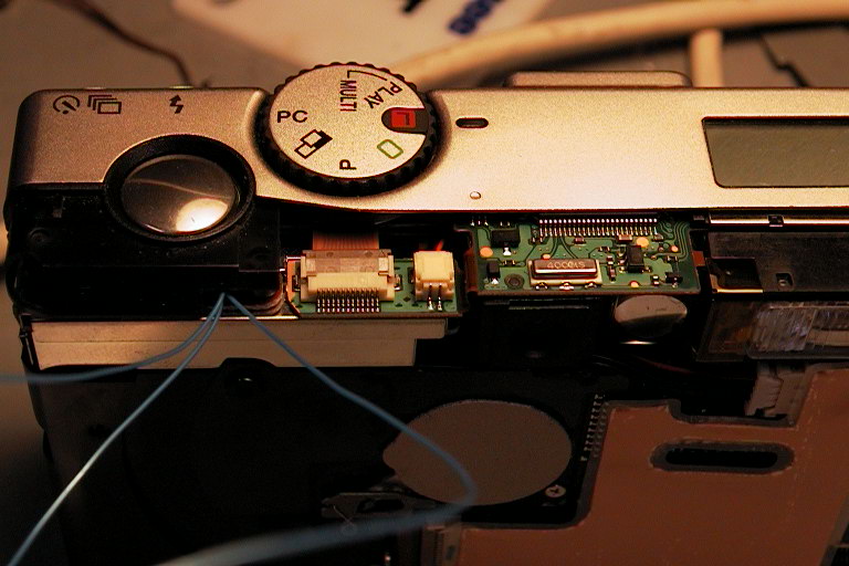
When you get the front skin off, you will be able to see the control
panel connector. Until you gently lift its retaining clip, you won't
be able to remove the rear skin. The shot to the right shows the camera
with the front skin off and the one to the left shows the retaining clip
lifted. The little blue wires sticking out of the front are my additions.
A factory fresh unit will not have them.
The controls will come off with the rear skin. |
 |
Bottom and Back
|
Front
|
Left Side
|