Stereo slide viewers can mean different things to different people. Each of us has a different set of “must have” features. Some commonly mentioned features are:
- Range of focus

- Accuracy of colors
- Limited distortion
- Eye relief
- Interocular adjustments
- Field of view
Different people value different features. No single viewer is going to make everyone happy.
There are those who strive to realistically recreate the the scene the camera saw at the time the image was made. I have, however, long been intrigued by wide-angle viewing regardless of the focal length of the lenses on the camera. I’ve wanted to get closer to the image and become part of it.
One of my experiments on this path involved replacing the lenses in a 3D-World focusing viewer with 60mm lenses. The resulting viewer looked just like the original, and it brought me closer to my images. That, however, is a topic for a different posting.
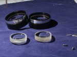
A posting to the MF3D mailing list in October 2011 and a subsequent phone conversation with Don Lopp convinced me to try a different approach. It starts with 50mm diameter binocular objectives, and 39mm achromatic eye pieces. The two elements are placed about 25mm apart. The  alignment of the two elements needs to be pretty precise. Deviations in the planes of the lenses or optic centers become apparent very quickly.
I started by hand-holding the elements above a slide. With two elements per eye, this wasn’t very practical and I mounted the elements in two pieces of wood. By placing them parallel to each other, at least the alignment was constrained in one dimension and everything was easier to hold. With a little trial and error, the lens boards were balanced on a section of cardboard which gave a fairly well focused image. The range of focus was very small, so inaccuracies in the cardboard,  tape and plywood construction were obvious. The resulting image, however, was big enough to keep me engaged and urge me to continue the experiment.
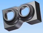
My brief efforts with hand tools had shown that I was not going to be able to achieve the required precision and alignment required to get the best out of my lens elements. I chose to pursue 3D-printing as a way to create a prototype with the correct tolerances. With no practical experience with 3D modeling or CAD, I was still able to work with a trial version of Autodesk Inventor and produce a viable model in exactly a month.
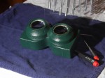
Printing the model required a week and cost about $100. When it came out of the shipping box, the lens elements fit in with only extremely minor sanding to the plastic. The resulting image through the viewer was superior to the plywood/cardboard version and justified the investment of time and money in the 3D design and printing.
Next Time: Dimensions, the viewing experience, and the next phase
