|
|
I have included file sizes in the image links. Please take a moment to check these sizes before you begin downloading images for viewing. Several of the JPS files are very large and will be painful to download over a modem link. The images are presented in cross-eye
and anaglyph format. If you prefer a different format or size, please give
the Stereoscope applet a try. |
|
|
|
|
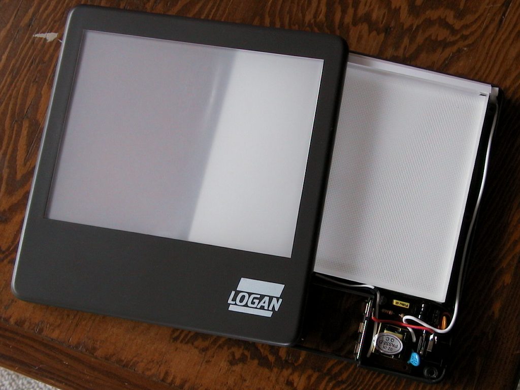
Retail Light
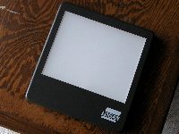 Several companies place their name on
a 4"x5"
thin light panel. I have seen the
same product from both Kalt and Logan. I chose the Logan product for this
project because it is significantly less expensive than the others and includes a suitable
AC to 9VDC adapter in the price. The panel has a few characteristics that
are worth mentioning. It:
Several companies place their name on
a 4"x5"
thin light panel. I have seen the
same product from both Kalt and Logan. I chose the Logan product for this
project because it is significantly less expensive than the others and includes a suitable
AC to 9VDC adapter in the price. The panel has a few characteristics that
are worth mentioning. It:
-
uses a fluorescent lamp
-
operates at 9VDC
-
is about 1/4 stop brighter at the top than the bottom
-
takes 60-90 seconds from initial power on to achieve full brightness
Before gutting the viewer for this project, I performed some measurements on it and found :
|
 |
The brightness measurements were made in the center of the panel 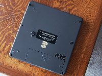 with my Sekonic L-208 after the
panel was up to full brightness. As you may determine from the above
chart, I'm not to religious about running my panel at 9V. I routinely
operate it 12V and have tried it at 14V. We can also see that the harder
we push it, the more efficient it becomes. When the voltage doubles (from
6V to 12V), the current consumption is slightly more than doubled, but the light
output increases two and a half times.
with my Sekonic L-208 after the
panel was up to full brightness. As you may determine from the above
chart, I'm not to religious about running my panel at 9V. I routinely
operate it 12V and have tried it at 14V. We can also see that the harder
we push it, the more efficient it becomes. When the voltage doubles (from
6V to 12V), the current consumption is slightly more than doubled, but the light
output increases two and a half times.
This is all well and good, but to do anything interesting with this light, we are going to have to get inside it. To do so, we flip it over and remove six screws from the bottom. There are four #1 and two #0 screws, so be sure you have the right tools on hand.
With the screws out, you can flip the unit back over and lift the face off. In it you will find:
In the base:
|
In the lid:
|

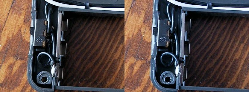

The concept here is the fluorescent tube lights the upper
edge of the acrylic panel and the light is reflected forward by the:
The thin diffuser sheet evens the light reflected out of the front of the acrylic panel and hides the white dots on the back of it. The white shims behind the reflective sheet keep it in full contact with the acrylic panel and the hard frosted sheet glued into the lid protects everything else from external damage. |
If you decide to put your panel back together, everything should slip easily
back into place and be ready to screw back together. As you reassemble, be
very careful not to damage the insulation on any of the wires. The
Fluorescent operates at very high voltages which need to be correctly
contained. Be aware of dust and dirt as you reassemble. Any dirt
that gets between the reflector and the acrylic panel will probably be
invisible, but anything that touches the diffuser sheet will certainly be
visible.
Treat the diffuser sheet with respect. It is very easily damaged and very difficult to replace. We have important plans for it and need it in pristine condition. It would be safest to remove it and keep it safely in an envelope until the final assembly.
When deciding if this was a viable project, I cut a
"dummy" light from plywood. Now our job is to take that 10mm acrylic panel and cut it down to match the size
of our prototype plywood. Next ![]()
[ Top of Viewer Project ]