|
|
I have included file sizes in the image links. Please take a moment to check these sizes before you begin downloading images for viewing. Several of the JPS files are very large and will be painful to download over a modem link. The images are presented in cross-eye
and anaglyph format. If you prefer a different format or size, please give
the Stereoscope applet a try. |
|
|
|
|
[ Back ] [ Next ]
Routing the new control wires
My original intention had been to use the NTSC video out jack on the left side of the camera to get the shutter release signals into the camera. I figured that I could cut the circuit board traces feeding this jack, and touch solder my new lead onto them. After seeing inside (and breaking a connector off of a circuit board on another A5), I realized that this approach was too ambitious. An external connector seemed to be a more reasonable solution.
To this end, I ran the control wires back under the "tethered" edge of the little circuit board, and around the upper left corner of the camera body. This required some nudging and careful arrangement of the new wires. It took a couple of tries to get the leads correctly placed so that the board would remount properly. At last it was fully seated, and I secured it with its four screws. This board must be in the correct location, and fully seated for the command dial and shutter buttons to work.
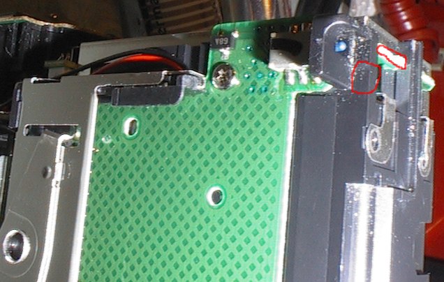 Using
a Dremel tool and a very small bit, I ground down a small section
of excess circuit board (upper right red circle in the photo) to allow
better wire access. Then I ground a small notch in the plastic just
below the CF door interlock switch. For version one (wire wrap wire) very
small notches are all that is required here. For version two, however, the
edge of the circuit board had to be ground down flush with the shielding in
order to gain enough space for the cable to pass through. A small notch in the CF door completed the
access path.
Using
a Dremel tool and a very small bit, I ground down a small section
of excess circuit board (upper right red circle in the photo) to allow
better wire access. Then I ground a small notch in the plastic just
below the CF door interlock switch. For version one (wire wrap wire) very
small notches are all that is required here. For version two, however, the
edge of the circuit board had to be ground down flush with the shielding in
order to gain enough space for the cable to pass through. A small notch in the CF door completed the
access path.