|
|
I have included file sizes in the image links. Please take a moment to check these sizes before you begin downloading images for viewing. Several of the JPS files are very large and will be painful to download over a modem link. The images are presented in cross-eye
and anaglyph format. If you prefer a different format or size, please give
the Stereoscope applet a try. |
|
|
|
|
[ Back ] [ Next ]
Center Section
Now is the opportunity to define the spacing of your twin. When standing in their normal orientation, the A100 is 57 mm high. When mounted top to bottom, and I am doing, this would equate to a stereo base of 57 mm. I felt this was a little narrow and chose to increase the base by ½" (12.7 mm). By adding a ½" spacer between the two cameras, I would have a more normal lens separation and I would have a gap into which I could cram any excess wire length.
My first choice for spacer material was styrene. Styrene is easy to work with, light, and (when chemically welded to the camera
cases) horrifically strong. Of course, strip styrene is unavailable in
Juneau. Choice two was aluminum box channel. A section ½" x
1½" would be almost as light as styrene, not as easy to work or
glue, but still provide a space to stash extra wire. Of course in Juneau, aluminum
box channel was only available in ¾" square. So I settled on what was
available in Juneau, and that was ½" x 1½" solid aluminum
bar. I cut a length as long as the camera and milled a channel out of its
center with my trusty hand drill and Dremel tool. The work would
have gone much faster with a drill press or a milling machine but one uses the
tools available to the job required.
Styrene is easy to work with, light, and (when chemically welded to the camera
cases) horrifically strong. Of course, strip styrene is unavailable in
Juneau. Choice two was aluminum box channel. A section ½" x
1½" would be almost as light as styrene, not as easy to work or
glue, but still provide a space to stash extra wire. Of course in Juneau, aluminum
box channel was only available in ¾" square. So I settled on what was
available in Juneau, and that was ½" x 1½" solid aluminum
bar. I cut a length as long as the camera and milled a channel out of its
center with my trusty hand drill and Dremel tool. The work would
have gone much faster with a drill press or a milling machine but one uses the
tools available to the job required.
I placed my bar against the base of the right camera and ran its wire "tails" through the slot and over to the waiting left camera.
Left Wires
Disassembly of the left camera goes just the same as the right. Don't
forget to discharge the flash capacitor! 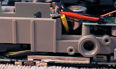 Then
comes the delicate job of getting the wires where they need to be. The two
power supply wires can be fed down through the gap behind the CF socket.
They can then be routed around the corner and up behind the grey plastic camera
frame. After some study, I determined that the best place to connect them
was exactly the same spots as had been used in the right hand camera, namely the
positive battery terminal and the negative lead on the power supply board.
Then
comes the delicate job of getting the wires where they need to be. The two
power supply wires can be fed down through the gap behind the CF socket.
They can then be routed around the corner and up behind the grey plastic camera
frame. After some study, I determined that the best place to connect them
was exactly the same spots as had been used in the right hand camera, namely the
positive battery terminal and the negative lead on the power supply board.
The wires for the shutter button can be assembled exactly as it was for the
right hand camera. After stripping the ends, tin them with just a bit of
solder and trim them very short. Tack them down to exactly the same spots
as  you
did in the right hand camera and everything will be perfect. The PC
board that carries the shutter button and CF door interlock is held in by only
one screw and restrained by only one ZIF connector. It is very easy to
remove from the camera for free solder access.
you
did in the right hand camera and everything will be perfect. The PC
board that carries the shutter button and CF door interlock is held in by only
one screw and restrained by only one ZIF connector. It is very easy to
remove from the camera for free solder access.
Reassembly is a little easier if you remove the shutter button from the front section of the case. It gives some extra clearance for the wires we've added, and you never know when that extra button may come in handy. Then, you will need the same sort of Dremel tool or file work to get the wires through the case.
At this point, you should have a fully functional twin. You can power up both cameras (each has its own power switch) and either shutter button should now trigger both cameras. Give it a try and see how it does. Watch for signs of over heating and don't put your face next to the cameras for the first few shots! If you have accidentally introduced a short in your power system, smoke, flames, or explosions can result.